

Industrial Chemical Gas Scrubber Boiler System – Integrated Emission Control & Heat Recovery
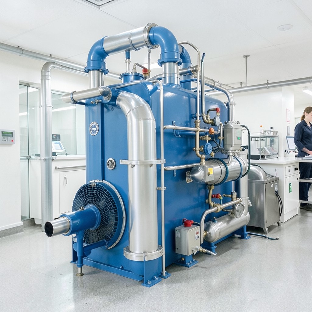
The industrial chemical gas scrubber boiler system combines high‑efficiency gas scrubbing with a fully‑rated boiler, delivering simultaneous pollutant removal and waste‑heat recovery for continuous‑process plants. Engineered for petrochemical, fertilizer, and pharmaceutical facilities, the unit captures acidic gases, particulates, and volatile organics while generating steam for turbine drive, heating, or drying applications. Its modular design allows seamless integration into existing production lines, minimizing downtime and maximizing overall plant efficiency.
How It Works – Dual‑Function Flow Path
1. Pre‑Scrubbing Stage – Inlet gas passes through a packed‑bed absorber where a tailored alkaline or neutralizing solution neutralizes acidic constituents (SO₂, HCl, HF). The liquid‑gas contact is optimized by high‑velocity distributors to achieve >99 % removal efficiency.
2. Heat‑Exchange Boiler – The cleaned gas, still carrying residual thermal energy, flows into a water‑tube boiler. Counter‑flow heat exchangers transfer heat to feedwater, producing saturated or super‑heated steam on demand.
3. Condensate Recovery – Scrubber effluent is routed to a condensate treatment module, enabling water recycling and reducing discharge fees.
4. Control Loop – A PLC‑based system continuously monitors pH, temperature, pressure, and flow, automatically adjusting reagent dosing and boiler firing rates to maintain target parameters.
Technical Specifications (customizable per order)
| Parameter | Typical Range | Unit |
|---|---|---|
| Gas Flow Capacity | 5 000 – 50 000 | Nm³/h |
| Steam Output | 2 – 30 | t/h |
| Removal Efficiency (SO₂, HCl, HF) | ≥99.5 | % |
| Operating Pressure (Boiler) | 0.7 – 2.5 | MPa |
| Material of Construction | SS304, SS316L, Hastelloy® C‑276 | – |
| Control System | PLC with HMI, Modbus/TCP, OPC-UA | – |
| Certifications | ASME, ISO 9001, CE (optional) | – |
*All figures are indicative. Final data are defined during the engineering phase to match plant‑specific conditions.
Application Scenarios
- Petrochemical cracking units – capture HCl and SO₂ while supplying steam to feedwater heaters.
- Fertilizer production – neutralize ammonia slip and recover heat for process drying.
- Pharmaceutical synthesis – maintain strict emission limits and provide clean‑steam for aseptic environments.
- Metal finishing lines – scrub acid mist and reuse waste heat for pre‑heat furnaces.
Each installation can be tailored as a skid‑mounted package or in‑situ retrofit, ensuring compliance with local environmental regulations without sacrificing plant throughput.
Competitive Advantages
• Integrated Design – Eliminates the need for separate scrubber and boiler, cutting capital cost by up to 30 %.
• Modular Scalability – Capacity can be increased in 10 % increments via parallel units, supporting future plant expansion.
• Energy Recovery Ratio – Typical heat‑recovery efficiency exceeds 85 %, translating into lower fuel consumption and CO₂ emissions.
• Robust Compliance – Designed to meet or exceed EPA, EU‑EIA, and local stack‑emission limits; optional CE marking available for European projects.
Frequently Asked Questions
What is the minimum order quantity (MOQ) for a custom‑engineered system?
Our engineering team can design units as small as 5 000 Nm³/h gas capacity. MOQ is based on the selected material grade and control package, typically one complete skid‑mount unit.
Can the system be adapted to handle specific corrosive gases?
Yes. Material selections such as Hastelloy® C‑276 or Monel® can be specified, and reagent dosing can be tuned for gases like HF, HCl, or SO₂ to meet target removal efficiencies.
What is the typical lead time from order to delivery?
Standard lead time ranges from 15 to 45 days, depending on configuration complexity and material availability. Expedited schedules are possible with prior notice.
What warranty and after‑sales support are provided?
All units ship with a 24‑month comprehensive warranty covering parts, workmanship, and control software. Our global service network offers on‑site training, spare‑part logistics, and 24 h technical assistance.
Ready to reduce emissions and capture valuable steam in one streamlined solution?
Contact Our Engineering Team Today