

Spiral Fin Tube Economizer for Chemical Boiler Plant
Our spiral fin tube economizer for chemical boiler plant is engineered to capture residual heat from flue gases and return it to the feed‑water circuit, dramatically improving overall plant efficiency. Designed for the rigorous demands of chemical processing, the unit tolerates aggressive condensate, high‑temperature differentials, and continuous duty cycles while meeting international safety and environmental standards.
Typical Application Scenarios
- **Petrochemical refineries** where steam generation runs 24/7 and fuel costs are a primary concern.
- **Pharmaceutical manufacturing** facilities that require precise temperature control and low‑scale fouling.
- **Specialty chemicals** plants with high‑purity water loops and stringent emissions regulations.
- **Integrated chemical complexes** that combine multiple boiler units and need a modular heat‑recovery solution.
In each case, the spiral fin tube design maximizes heat‑transfer surface area within a compact footprint, enabling retrofit installations without major civil works.
Product Overview
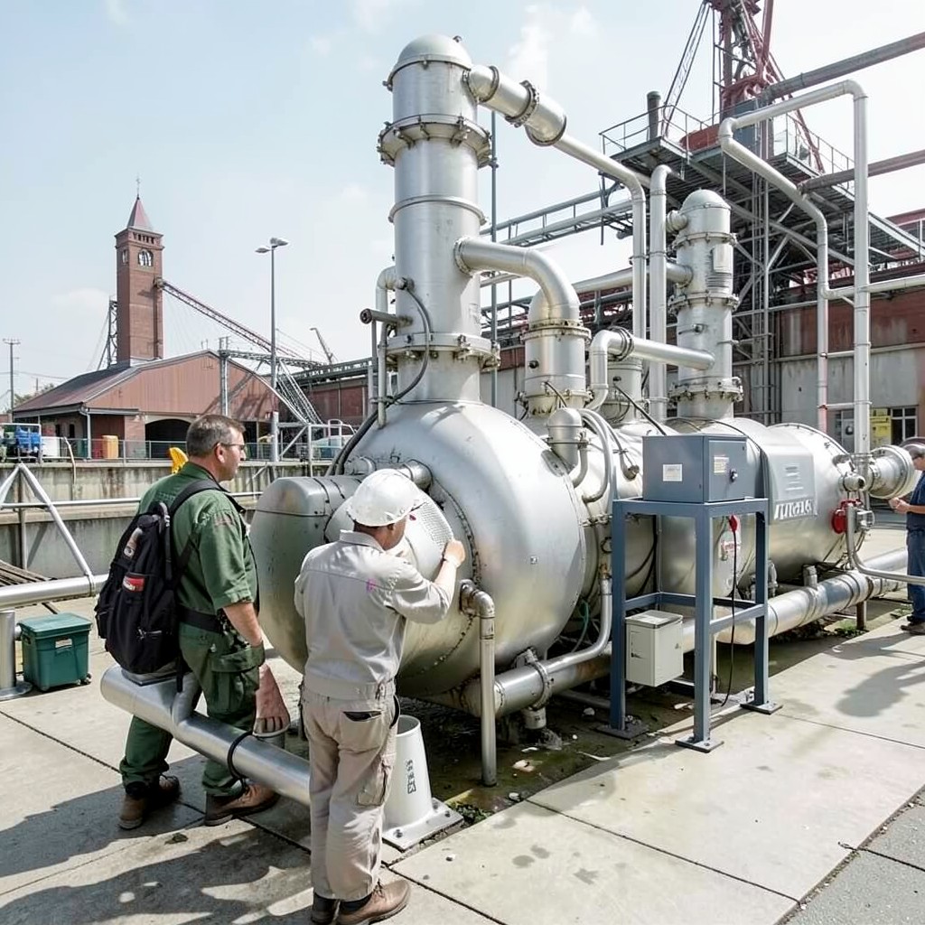
The economizer consists of a stainless‑steel shell housing a series of spiral‑wound finned tubes. Water flows through the tube bundle while the flue gas passes over the fins, extracting heat efficiently. Key construction features include:
- 304/316L stainless‑steel tubes and fins for corrosion resistance.
- Modular frame allowing parallel or series connection.
- Expandable inlet/outlet flanges to match existing boiler piping.
- Integrated pressure‑relief and venting provisions.
All components are fabricated to meet ASME Section VIII and PED (EU) requirements, ensuring seamless integration into certified boiler systems.
How It Works
Flue gas exiting the combustion chamber enters the economizer at temperatures typically between 150 °C and 250 °C. As the gas flows over the spiral fins, its thermal energy is transferred to the water circulating inside the tubes. The spiral geometry forces a turbulent flow around each fin, boosting the overall heat‑transfer coefficient by up to 30 % compared with straight‑tube designs. The pre‑heated water then returns to the boiler feed pump, reducing the fuel required to achieve steam set‑points.
Because the finned tubes are spaced to encourage natural drainage, condensate does not accumulate, minimizing corrosion risk and maintenance intervals.
Typical Specifications (customizable per order)
| Parameter | Standard Range | Unit |
|---|---|---|
| Design Pressure (water side) | 1.0 – 2.5 | MPa |
| Maximum Flue‑Gas Temperature | 150 – 300 | °C |
| Heat Transfer Area | 10 – 150 | m² |
| Overall Heat‑Transfer Coefficient | 800 – 1 200 | W/m²·K |
| Material (tubes/fins) | 304/316L SS | — |
| Connection Size | DN50 – DN200 | — |
All dimensions, materials, and pressure ratings can be tailored to match your plant’s design specifications.
Competitive Advantages
- Higher thermal efficiency: Spiral fin geometry provides a larger heat‑exchange surface in a smaller envelope.
- Robust corrosion resistance: Use of 316L stainless steel for aggressive chemical environments.
- Reduced footprint: Compact design fits into existing boiler rooms without extensive re‑layout.
- Fast lead time: Standard models ship within 15‑45 days; custom designs available on a 6‑week schedule.
- Full compliance: Certified to ASME, PED, and ISO 9001 quality management systems.
These factors translate into lower operating costs, longer service intervals, and faster ROI for chemical boiler plants.
FAQ
What is the minimum order quantity (MOQ) for a custom spiral fin tube economizer?
We typically accept orders starting at one unit for standard configurations. For bespoke designs, the MOQ is five units to optimize tooling and engineering resources.
Can the economizer be fabricated from alternative alloys?
Yes. In addition to 304/316L stainless steel, we can provide duplex, titanium, or nickel‑based alloys on request, subject to additional lead time and cost.
What warranty and after‑sales support are offered?
All units ship with a 12‑month limited warranty covering material and workmanship. We also provide on‑site commissioning assistance and a network of service partners for routine maintenance.
How long does it take to deliver a standard model?
Typical lead time for standard models is 15‑45 days after order confirmation, depending on quantity and destination.
Ready to Boost Your Plant’s Efficiency?
Contact our engineering team today to discuss specifications, obtain a quotation, or schedule a technical review. Click the button below or email us at sales@yourcompany.com.