

Optimising Energy Efficiency in Power Plants
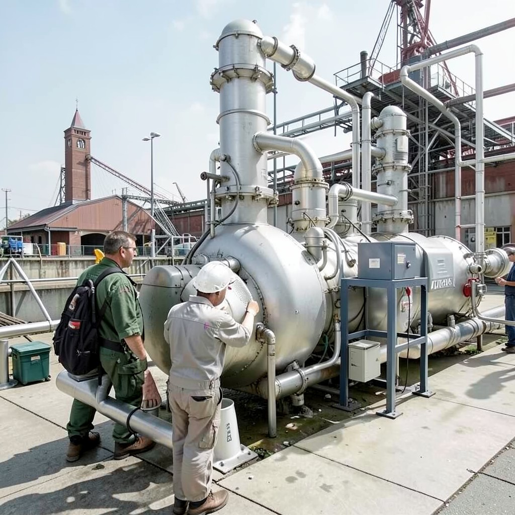
Industrial facilities that run coal‑fired boilers face rising fuel costs and stricter emissions limits. A waste heat recovery system for coal boiler flue gas captures thermal energy that would otherwise be lost up the stack, converting it into useful steam or hot water for process heating, district heating, or power generation. Our engineered solution integrates seamlessly with existing boiler trains, delivering measurable fuel savings and carbon‑footprint reduction from day one.
Where It Adds Value
The system is deployed in a range of settings where coal‑fired boilers dominate: large‑scale utility power stations, cement kilns, steel mills, and petrochemical complexes. In each case the flue‑gas temperature (typically 150‑250 °C) provides a reliable heat source for a compact, low‑maintenance heat‑exchanger train. By routing this energy to a secondary loop, plants can:
- Reduce coal consumption by 5‑12 % per operating hour.
- Lower SO₂, NOₓ and CO₂ emissions in line with local regulations.
- Free up boiler capacity for higher load or additional processes.
- Extend the life of boiler components by moderating exhaust temperature.
How It Works – From Flue Gas to Steam
1. Heat‑exchange module – A stainless‑steel, finned‑tube array is inserted directly into the flue‑gas path. The high‑temperature gas transfers heat to a closed‑loop water circuit without pressure loss.
2. Steam generation – The heated water reaches the boiling point within a compact boiler bank, producing saturated or super‑heated steam ready for turbine feed, process heating, or district‑heat supply.
3. Control & monitoring – Integrated sensors feed real‑time temperature, flow, and pressure data to a PLC‑based control panel, allowing operators to optimise extraction ratios while protecting boiler integrity.
4. Exhaust cooling – After heat extraction, the flue gas temperature drops to 80‑100 °C, reducing thermal stress on downstream ductwork and facilitating easier compliance with stack‑temperature limits.
Typical Specifications (customizable per order)
| Parameter | Standard Range | Units |
|---|---|---|
| Design steam output | 2 – 200 | t/h |
| Flue‑gas inlet temperature | 150 – 250 | °C |
| Thermal efficiency | 10 % – 18 % | % |
| Material construction | 304/316L SS, Inconel‑625 (high‑temp zones) | – |
| Duty cycle | Continuous 24 h/365 d | – |
| Control interface | PLC/HMI, Modbus/TCP, Profibus | – |
All parameters are adjustable to match the specific boiler size, flue‑gas composition, and steam demand of your plant. Engineering teams work closely with customers to validate performance through CFD modelling before final fabrication.
Why Choose Our waste heat recovery system for coal boiler flue gas?
Proven reliability. Our units have been in service for over a decade in harsh, high‑temperature environments with less than 0.2 % unscheduled downtime.
Global compliance. Designs meet IEC 60335, ASME‑BPVC Section VIII, and are CE‑marked where applicable, ensuring smooth approval across jurisdictions.
Scalable engineering. From 2 t/h to 200 t/h steam output, the modular layout allows phased expansion without major plant shutdowns.
Turnkey support. We provide site‑assessment, detailed engineering, installation supervision, and a 24 / 7 spare‑parts hotline.
Cost‑effective ROI. Typical payback periods range from 18 to 36 months based on fuel‑price differentials and emission‑credit incentives.
Frequently Asked Questions
What is the minimum order quantity (MOQ) for a custom‑designed unit?
We have no strict MOQ; each system is engineered to the specific plant’s heat‑recovery potential. The design phase starts after a preliminary feasibility study, which is free of charge.
Can the system be integrated with existing control architectures?
Yes. Our HMI/PLC interfaces support Modbus/TCP, Profibus, and OPC-UA, enabling seamless communication with legacy DCS or SCADA platforms.
What is the typical lead time from order to commissioning?
Standard units are delivered within 30‑45 days after final design approval. Highly customized projects may require 60‑90 days, depending on material selections and site logistics.
What warranty and after‑sales service are provided?
All installations come with a 24‑month comprehensive warranty covering manufacturing defects and on‑site performance verification. Extended service contracts are available on a yearly basis.
Ready to capture lost energy and boost your plant’s profitability?
Contact Our Engineering Team Today