English
- Afrikaans
- Albanian
- Amharic
- Arabic
- Armenian
- Azerbaijani
- Basque
- Belarusian
- Bengali
- Bosnian
- Bulgarian
- Catalan
- Cebuano
- Corsican
- Croatian
- Czech
- Danish
- Dutch
- English
- Esperanto
- Estonian
- Finnish
- French
- Frisian
- Galician
- Georgian
- German
- Greek
- Gujarati
- Haitian Creole
- hausa
- hawaiian
- Hebrew
- Hindi
- Miao
- Hungarian
- Icelandic
- igbo
- Indonesian
- irish
- Italian
- Japanese
- Javanese
- Kannada
- kazakh
- Khmer
- Rwandese
- Korean
- Kurdish
- Kyrgyz
- Lao
- Latin
- Latvian
- Lithuanian
- Luxembourgish
- Macedonian
- Malgashi
- Malay
- Malayalam
- Maltese
- Maori
- Marathi
- Mongolian
- Myanmar
- Nepali
- Norwegian
- Norwegian
- Occitan
- Pashto
- Persian
- Polish
- Portuguese
- Punjabi
- Romanian
- Russian
- Samoan
- Scottish Gaelic
- Serbian
- Sesotho
- Shona
- Sindhi
- Sinhala
- Slovak
- Slovenian
- Somali
- Spanish
- Sundanese
- Swahili
- Swedish
- Tagalog
- Tajik
- Tamil
- Tatar
- Telugu
- Thai
- Turkish
- Turkmen
- Ukrainian
- Urdu
- Uighur
- Uzbek
- Vietnamese
- Welsh
- Bantu
- Yiddish
- Yoruba
- Zulu
 Co., Ltd.")
Telephone: +86 13120555503
Email: frank@cypump.com


Apr . 01, 2024 17:55 Back to list
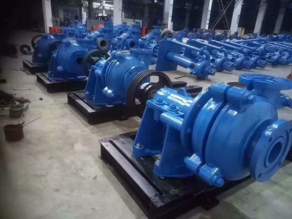
Slurry Pump Data Sheet Performance Analysis
Introduction
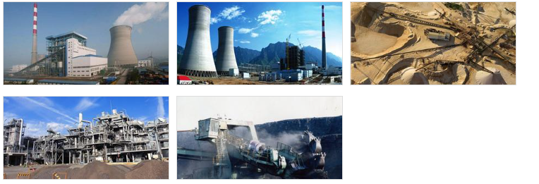
Slurry pump data sheets are critical documentation for specifying and selecting pumps designed to transport abrasive and erosive fluids – commonly referred to as slurries – across diverse industrial applications. These applications range from mining and mineral processing to wastewater treatment, chemical processing, and dredging. The data sheet encapsulates essential performance characteristics, material specifications, and operational parameters required for optimal pump selection and system integration. The core function of a slurry pump differs significantly from that of a centrifugal pump handling clean fluids, requiring specialized design considerations to mitigate wear, erosion, and clogging. A properly completed and analyzed data sheet minimizes risks associated with premature failure, inefficient operation, and costly downtime. Understanding the intricacies detailed within these sheets is paramount for process engineers, procurement specialists, and maintenance personnel responsible for slurry handling systems. This guide provides a comprehensive overview of the information contained within a typical slurry pump data sheet, delving into the underlying principles, material science, and engineering considerations.
Material Science & Manufacturing
The performance and longevity of a slurry pump are fundamentally dictated by the materials of construction. Commonly employed materials include high-chromium cast iron (typically 13-28% Cr) for impeller and casing components, offering excellent abrasion resistance. For severely abrasive slurries, or corrosive environments, duplex stainless steels (e.g., 2205, 2507) and high-alloy stainless steels (e.g., 316, 904L) are utilized, balancing corrosion resistance with acceptable wear characteristics. Elastomeric liners, typically natural rubber or synthetic rubbers like EPDM or polyurethane, are often employed to protect the pump casing from impact and erosion, especially with large particle sizes. Manufacturing processes vary depending on component complexity. Casings are often produced via sand casting or investment casting, allowing for complex geometries. Impellers can be manufactured using similar casting processes, or, for smaller pumps and higher alloy materials, centrifugal casting or even forging. Welding is frequently used in fabrication, requiring qualified welders and stringent quality control procedures to prevent defects and maintain corrosion resistance. Key parameter control during manufacturing includes hardness testing of wear surfaces (Brinell, Vickers), chemical composition verification via spectroscopy, and dimensional inspection utilizing Coordinate Measuring Machines (CMM) to ensure adherence to specified tolerances. The selection of the appropriate gasket material (e.g., Viton, PTFE) is also crucial for chemical compatibility and preventing leakage. Liners are typically applied via vulcanization, a process requiring precise temperature and pressure control.
Performance & Engineering
Slurry pump performance is characterized by several key parameters detailed on the data sheet. Head (expressed in meters or feet) represents the energy imparted to the slurry per unit weight, determining the pumping height. Flow rate (expressed in m³/hr or GPM) defines the volume of slurry delivered per unit time. The pump’s power requirement (kW or HP) is directly related to head and flow rate, and significantly impacts operating costs. Net Positive Suction Head Required (NPSHr) is a critical parameter, dictating the minimum pressure required at the pump suction to prevent cavitation – a phenomenon causing impeller damage and reduced performance. The pump’s efficiency, typically expressed as a percentage, reflects the ratio of hydraulic power output to shaft power input. Solids Handling Capability (particle size and concentration) is a key design consideration, influencing impeller geometry and casing wear life. Force analysis, particularly stress analysis of the impeller and casing, is crucial during the design phase to ensure structural integrity under operating conditions. Environmental resistance considerations include temperature limitations, exposure to corrosive substances, and potential for abrasion from suspended solids. Compliance requirements vary by region and application, with common standards relating to safety (e.g., ATEX for explosive atmospheres), environmental protection (e.g., emission limits), and materials traceability. Proper impeller design and casing volute geometry minimize turbulence and energy losses, maximizing hydraulic efficiency. Selection of the correct pump curve, based on the system’s required operating point, is essential for optimal performance and minimized wear.
Technical Specifications
| Parameter | Unit | Typical Range | Notes |
|---|---|---|---|
| Flow Rate | m³/hr | 10 - 1000 | Dependent on pump size and impeller diameter. |
| Head | m | 5 - 80 | Determines the pumping height and system pressure. |
| Power | kW | 1.5 - 200 | Influenced by flow rate, head and efficiency. |
| NPSHr | m | 1 - 10 | Critical to avoid cavitation. Must be lower than NPSHa (Available). |
| Maximum Solids Size | mm | 6 - 100+ | Determines impeller design and pump selection. |
| Slurry Concentration (by weight) | % | 5 - 70 | Higher concentrations increase wear rates. |
Failure Mode & Maintenance
Slurry pump failure modes are predominantly linked to abrasive wear, erosive wear, and corrosion. Impeller wear, particularly on the leading edge and vane tips, is common due to the impact of solid particles. Casing wear typically occurs in areas of high velocity and turbulence, such as the volute and suction/discharge connections. Mechanical seal failures are frequent, stemming from abrasion by solids or chemical incompatibility. Fatigue cracking can develop in the impeller or casing due to cyclical loading and stress concentrations. Degradation of elastomeric liners occurs through abrasion, chemical attack, and thermal cycling. Oxidation of metallic components, especially in corrosive environments, leads to material loss and structural weakening. Preventive maintenance is crucial. Regular inspection of impeller and casing wear is essential, alongside monitoring of seal performance and bearing temperatures. Lubrication schedules must be strictly adhered to. Periodic replacement of worn components (impellers, liners, seals) minimizes downtime and prevents catastrophic failures. Regular analysis of the slurry composition helps predict wear rates and optimize maintenance schedules. Implement a robust vibration analysis program to detect early signs of bearing or impeller imbalance. Proper pump alignment and foundation stability prevent excessive stress on the pump components.
Industry FAQ
Q: What is the significance of the NPSHr value on the data sheet, and how does it relate to system performance?
A: NPSHr (Net Positive Suction Head Required) represents the minimum pressure required at the pump suction to prevent cavitation. If the NPSHa (Net Positive Suction Head Available) in the system is less than the NPSHr, cavitation will occur, leading to impeller damage, noise, and reduced pump performance. Accurate NPSHr determination is crucial for preventing pump failure and ensuring stable operation.
Q: How does the slurry composition affect the choice of materials for the pump components?
A: The slurry composition dictates the required material resistance. Highly abrasive slurries necessitate hard materials like high-chromium cast iron. Corrosive slurries demand corrosion-resistant alloys such as duplex stainless steels or high-alloy stainless steels. The concentration and size of solid particles also influence material selection, particularly for impeller and liner materials.
Q: What is the impact of impeller diameter on pump performance?
A: Impeller diameter directly influences the pump’s head and flow rate. A larger impeller diameter generally increases head, while a smaller diameter favors higher flow rates. Selecting the appropriate impeller diameter is critical for matching the pump’s performance curve to the specific system requirements.
Q: How do I interpret the pump curve provided in the data sheet?
A: The pump curve graphically represents the relationship between flow rate, head, power, and efficiency. It allows you to determine the pump's operating point for a given system resistance curve. Selecting a pump operating near its Best Efficiency Point (BEP) maximizes efficiency and minimizes wear.
Q: What is the role of the casing liner in a slurry pump, and what material options are available?
A: The casing liner protects the pump casing from abrasion and erosion caused by the slurry. Common liner materials include natural rubber, EPDM, polyurethane, and ceramic coatings. The selection depends on the slurry's abrasiveness, chemical composition, and operating temperature. Liners significantly extend the pump’s service life.
Conclusion
The slurry pump data sheet serves as a foundational document for ensuring optimal pump selection and reliable operation. A thorough understanding of the parameters detailed within – encompassing flow rate, head, power, NPSHr, material specifications, and solids handling capabilities – is vital for mitigating risks associated with premature failure and maintaining process efficiency. Selecting the appropriate materials of construction, considering the slurry composition and operating environment, is paramount for maximizing pump lifespan and minimizing maintenance costs.
Moving forward, advancements in pump design and material science will continue to drive improvements in slurry pump performance and durability. Integration of computational fluid dynamics (CFD) for optimized impeller and casing geometries, coupled with the development of novel wear-resistant alloys and coatings, will enable even more effective slurry handling solutions. Continued emphasis on predictive maintenance and condition monitoring will further enhance reliability and reduce lifecycle costs.
-
Comprehensive Guide to Waterproof ORings for Optimal Sealing Solutions
News2026-06-09
-
best ejector pump for basement bathroom Material Science Manufacturing
News2026-06-28
-
bathroom ejector pump system Material Science Manufacturing
News2026-06-28
-
bathroom ejector pump Performance and Engineering
News2026-06-28
-
basement toilet ejector pump Performance Analysis
News2026-06-28
-
Septic Tank Pump Technology Analysis
News2026-06-28
-
Waste Tank Pump Performance Analysis
News2026-06-27
-
Sewer System Pump Out Material Science
News2026-06-27
-
Sewer Ejector Pit Performance Analysis
News2026-06-27
-
septic tank pumps for sale Performance Engineering
News2026-06-27
-
septic system with lift pump Performance Engineering
News2026-06-27
-
septic system sump pump Performance Analysis
News2026-06-26
-
septic pump company Performance Analysis
News2026-06-26
-
pumps water treatment Performance Analysis
News2026-06-26
-
pumps for septic tanks Material Science and Manufacturing
News2026-06-26


