
Apr . 01, 2024 17:55 Back to list
Oil Pressure Gauge how to connect a oil pressure gauge Performance Analysis
Introduction
An oil pressure gauge is a critical instrument for monitoring the health of an internal combustion engine and other hydraulic systems. It provides a direct reading of the oil pressure within the system, enabling early detection of potential failures such as oil pump malfunction, blocked oil passages, or excessive engine wear. Correct installation and understanding of operation are paramount for accurate readings and reliable engine performance. This guide provides a comprehensive overview of the principles of oil pressure gauge connection, focusing on material compatibility, installation procedures, common failure points, and relevant industry standards. The increasing complexity of modern engine management systems necessitates precise monitoring, making accurate oil pressure readings a foundational element of preventative maintenance and reliable operation across automotive, marine, and industrial applications. Misinterpretation of oil pressure readings, stemming from improper installation or gauge malfunction, can lead to catastrophic engine damage, underscoring the importance of a thorough understanding of the principles outlined herein.
Material Science & Manufacturing
Oil pressure gauges typically utilize a Bourdon tube, a curved, flattened tube that straightens proportionally to the pressure applied internally. These tubes are commonly manufactured from alloys of beryllium copper, steel (often carbon steel or stainless steel - 304/316 grades), or brass, each offering specific advantages concerning corrosion resistance, elasticity, and cost. The gauge housing is frequently constructed from steel with a protective coating (painting, plating, or powder coating) to resist environmental degradation. The connection port, crucial for interfacing with the oil system, is often brass or stainless steel to ensure compatibility with engine oil and threaded fittings. Manufacturing processes vary depending on the component. Bourdon tubes are formed through cold drawing and annealing processes to achieve the desired shape and spring characteristics. The housing undergoes deep drawing and stamping, followed by surface treatment. Connection fittings are produced via machining and thread rolling. Critical parameters in manufacturing include heat treatment to control material hardness and elasticity, and leak testing to ensure the integrity of the Bourdon tube and connections. The selection of sealing materials, such as nitrile rubber (NBR) or Viton (FKM), is critical for compatibility with different oil types (mineral, synthetic, vegetable-based) and operating temperatures. Failure to account for chemical compatibility can result in seal degradation and inaccurate readings.
Performance & Engineering
The performance of an oil pressure gauge is directly tied to its ability to accurately translate pressure into a readable format. Force analysis centers on the stress distribution within the Bourdon tube under pressure. The tube's wall thickness and radius of curvature are engineered to achieve a linear response within the specified pressure range. Environmental resistance is a major consideration; gauges are often tested for vibration, shock, and temperature cycling. Compliance requirements, particularly in automotive applications, demand adherence to standards regarding accuracy, repeatability, and safety. The gauge's mechanical linkage, converting tube movement to pointer deflection, must minimize friction and hysteresis for precise readings. Electrical resistance gauges utilize a variable resistor linked to the Bourdon tube, providing an electrical signal proportional to pressure. These gauges are more susceptible to electromagnetic interference (EMI) and require shielding. Thread sealing is crucial; PTFE tape or liquid thread sealant should be used to prevent leaks. The correct port size and thread type (NPT, BSPT, etc.) must be matched to the engine's oil pressure sending unit port. Proper venting is important to prevent pressure buildup in the gauge line. The gauge should be mounted securely to minimize vibration and ensure readability.
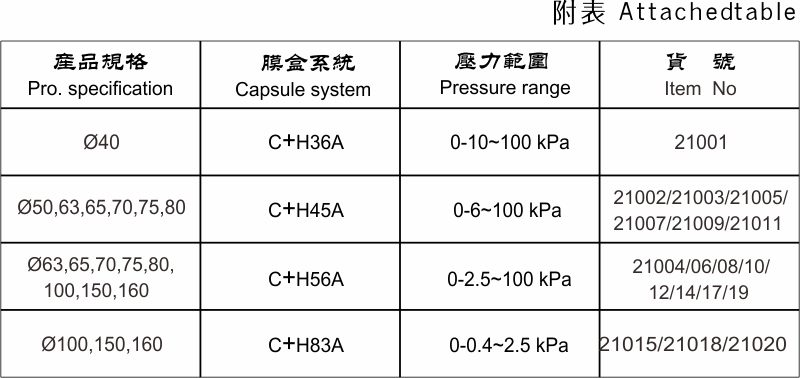
Technical Specifications
| Pressure Range (PSI) | Accuracy (±%) | Connection Size (NPT) | Operating Temperature (°F) |
|---|---|---|---|
| 0-100 | 2 | 1/8" | -40 to 200 |
| 0-3000 | 1.5 | 1/4" | -20 to 250 |
| 0-5000 | 1 | 1/4" | -40 to 250 |
| 0-6000 | 1 | 1/2" | -20 to 250 |
| 0-10000 | 0.5 | 1/2" | -40 to 200 |
| 0-20000 | 0.5 | 3/4" | -20 to 200 |
Failure Mode & Maintenance
Common failure modes for oil pressure gauges include Bourdon tube rupture due to overpressure, connection leaks resulting from thread damage or inadequate sealing, and mechanical failure of the linkage causing inaccurate readings. Fatigue cracking can occur in the Bourdon tube due to prolonged exposure to vibration and pressure cycling. Delamination of the dial face or protective coating can degrade readability. Oxidation and corrosion can affect the internal components, leading to sticking or seizing. Blockages in the gauge line, caused by debris or solidified oil, can also lead to inaccurate readings. Maintenance involves regular visual inspection for leaks, cracks, or damage. Periodically check the gauge zero point. If the gauge is exposed to harsh environments, consider applying a protective coating to the housing. Ensure the gauge line is free from kinks or restrictions. If the gauge consistently provides inaccurate readings, it should be replaced. When replacing a gauge, verify the compatibility of the new gauge with the existing oil system. Use appropriate thread sealant and torque specifications. Avoid subjecting the gauge to excessive shock or vibration. Periodic calibration against a known pressure standard is recommended for critical applications.
Industry FAQ
Q: What is the impact of oil viscosity on oil pressure gauge readings?
A: Oil viscosity directly impacts pressure readings. Higher viscosity oil requires more force to pump, resulting in higher pressure readings, particularly at startup. Lower viscosity oil provides less resistance and results in lower pressure readings. Therefore, it is crucial to use the oil viscosity recommended by the engine manufacturer and to understand that variations in viscosity due to temperature changes will affect the readings.
Q: How do I determine the correct pressure range for my application?
A: The correct pressure range should be selected based on the normal operating pressure of the system. The gauge should be selected such that the normal operating pressure falls within the middle third of the gauge's range for optimal accuracy. Exceeding the maximum pressure rating can lead to gauge failure and potential hazards.
Q: What type of thread sealant is recommended for oil pressure gauge connections?
A: PTFE (Teflon) tape or a liquid PTFE-based thread sealant is recommended. Avoid using sealants that contain silicone or other materials that could contaminate the oil system. Ensure the sealant is compatible with the oil being used.
Q: How can I troubleshoot a fluctuating oil pressure gauge reading?
A: Fluctuating readings can be caused by several factors, including air in the gauge line, a faulty oil pump, a clogged oil filter, or a malfunctioning gauge. First, bleed the gauge line to remove any air. If the problem persists, inspect the oil pump and filter. If those components are functioning correctly, replace the gauge.
Q: Is it acceptable to use an adapter to connect an oil pressure gauge with a different thread size?
A: Using an adapter is acceptable, provided it is of high quality and rated for the maximum pressure of the system. Ensure the adapter is made from compatible materials and is properly sealed to prevent leaks. Inferior adapters can fail, leading to dangerous leaks and inaccurate readings.
Conclusion
The accurate connection and interpretation of oil pressure gauge readings are fundamental to maintaining the health and longevity of internal combustion engines and hydraulic systems. This guide has detailed the critical aspects of gauge selection, material compatibility, installation procedures, and potential failure modes. Understanding the underlying principles of Bourdon tube mechanics, force analysis, and environmental resistance is paramount for ensuring reliable performance.
Moving forward, advancements in sensor technology are leading to the development of digital oil pressure gauges with increased accuracy, remote monitoring capabilities, and integration with engine management systems. Regular inspection and maintenance, coupled with adherence to relevant industry standards, remain crucial for preventing catastrophic failures and maximizing operational efficiency. Proper gauge selection and installation, based on the principles outlined herein, will continue to be essential for maintaining the integrity of critical systems.